|
|
|
|
|
|
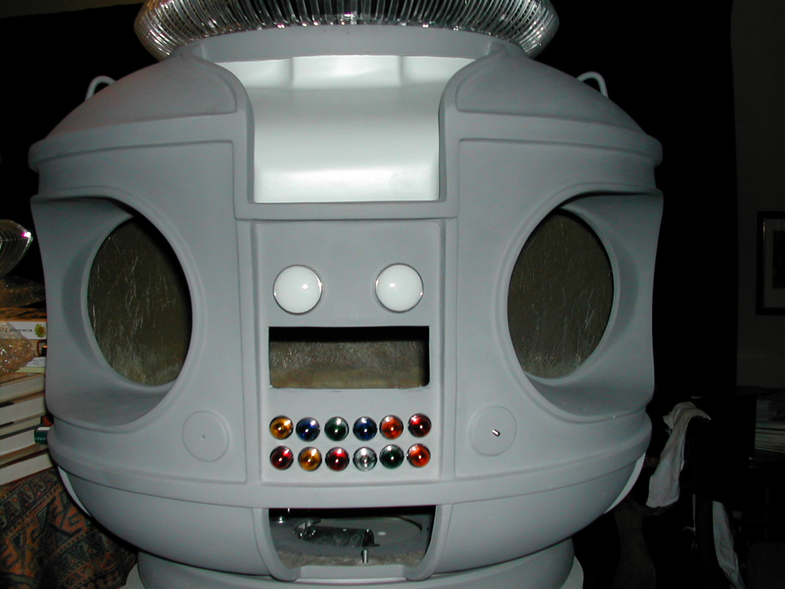
THE TORSO
This torso is beautifully made and finished. It has came sanded and primed. It would almost be ready to be painted but for a few minor tasks that must first be performed:
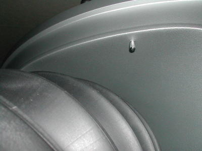
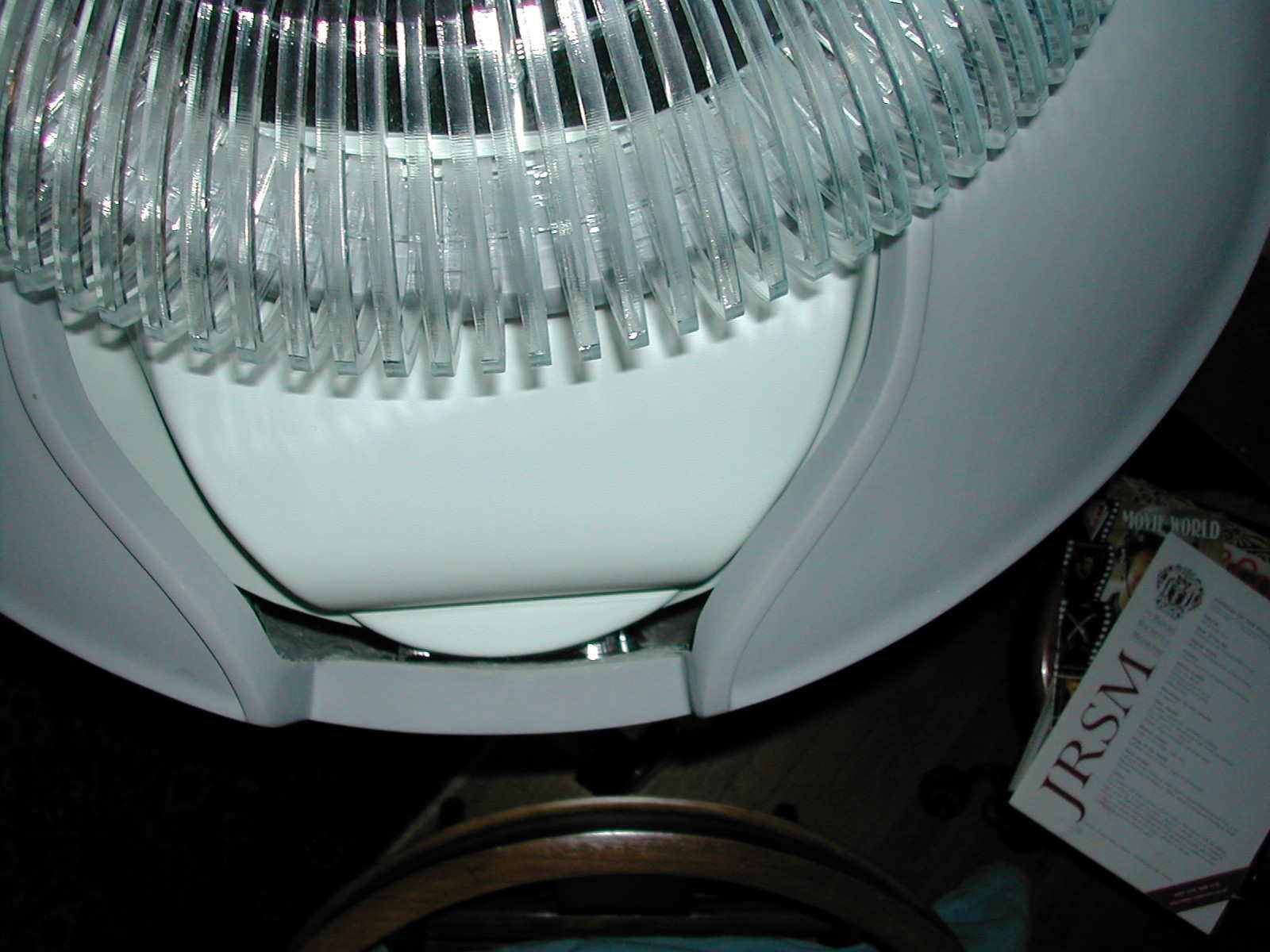
1. The top surface of the upper horizontal band requires sanding to create a ninety-degree angle with the side aspect of the band.
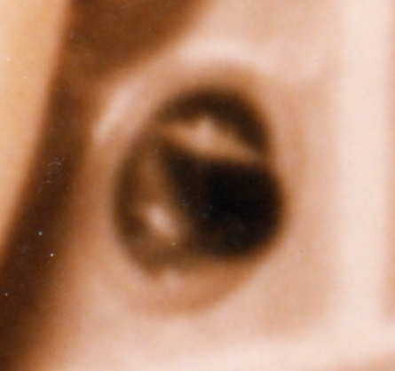
Note in
the photograph below how poorly shaped
the upper aspect of this band is. Sanding will fix it without much
trouble.
Unfortunately, sanding might remove so much fiberglass that the torso
will
be sliced in two. This will require a bit of fiber glassing on the
inside
of the torso and perhaps some sculpting with bondo on the outside.
Given
that most other B9 builders have had to do far more body work than this
to perfect their torsos, I feel very fortunate that this is all I have
to do.
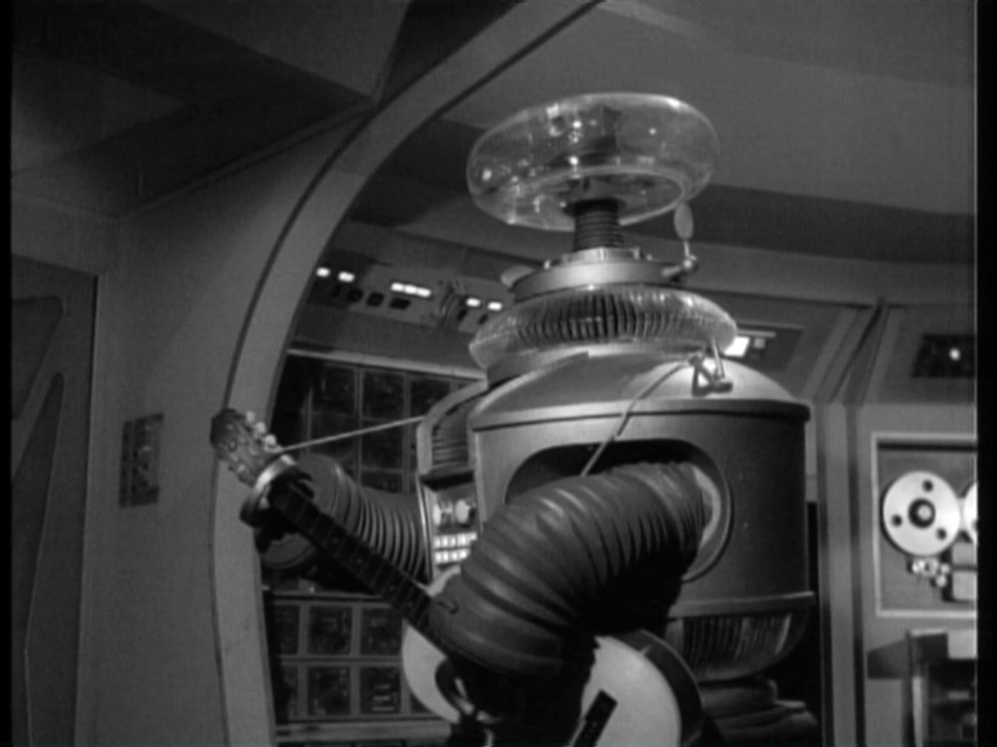
Note how much crisper this angle is in the
original
robot:
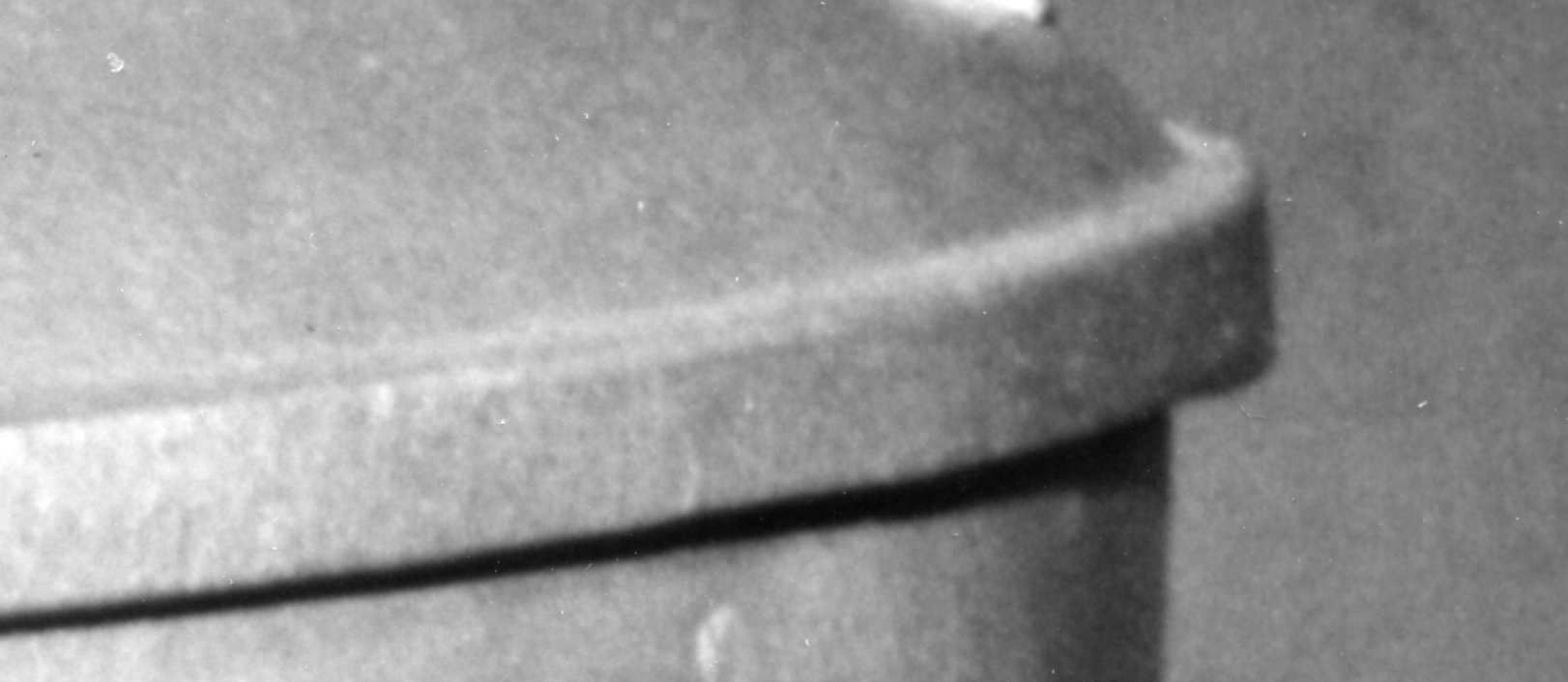
Thankfully,
the lower horizontal band at the bottom
of my robot's torso just
below the belly lights and about the vents is
perfect in this regard.
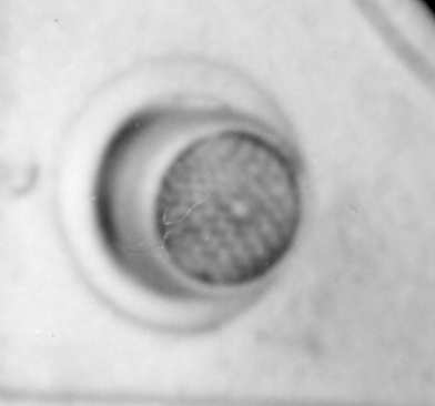
2. I need
to cut out the holes for the torso knob
and the torso microphone.
My torso has flat discs in these places, but
on the original robot, the disc for the torso knob is actually a raised
ring with an flat inner circle.
Note also that the torso knob in the second
photograph
has been changed to a tear drop-shaped knob. It is interesting that the
first torso knob is larger than the diameter of the inner margin of the
raised ring. I have a similar knob (courtesy of Craig Reinbrecht) and
am
familiar with its dimensions. It must be raised up from the bottom of
the
inner well using washers of some sort.
It is odd that my torso knob appears to be much larger than the original. Either my torso knob is too large or the torso ring is too small. Perhaps both are true. Further investigation may shed some light on this mystery.
For the
torso microphone, there is also a flat
raised ring, but inside this ring is a concave dish. Notice these
features
in this photograph:
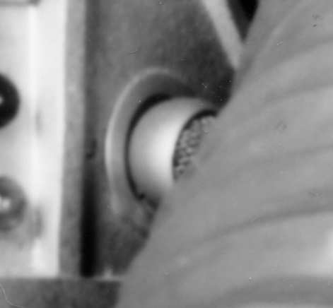
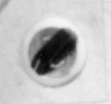
A socket has been cut out at the bottom of the
dish to accept the shaft of the microphone. Sometimes, in various
episodes
of Lost in Space, the microphone slips out of its socket
and
can be seen protruding.
Here is a list of some of the other projects required to finish the torso:
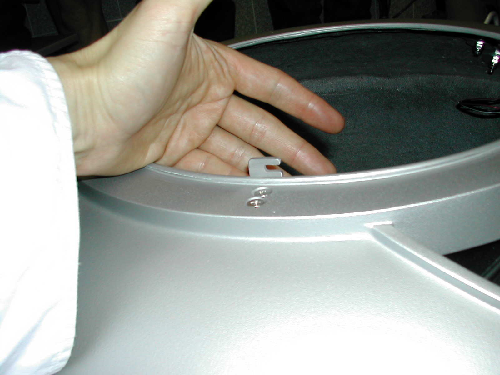
3. Cut out holes to receive the jacks for the power pack.
4. Insert
metal pegs into the ceiling and floor
of the arms sockets for the wrist latches.
This is a photograph of just such a peg in Craig
Reinbrecht robot.
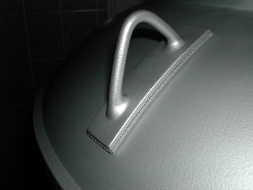
5. Add matting beneath the torso hooks as the original had, and as can be seen in Craig Reinbrecht's robot.
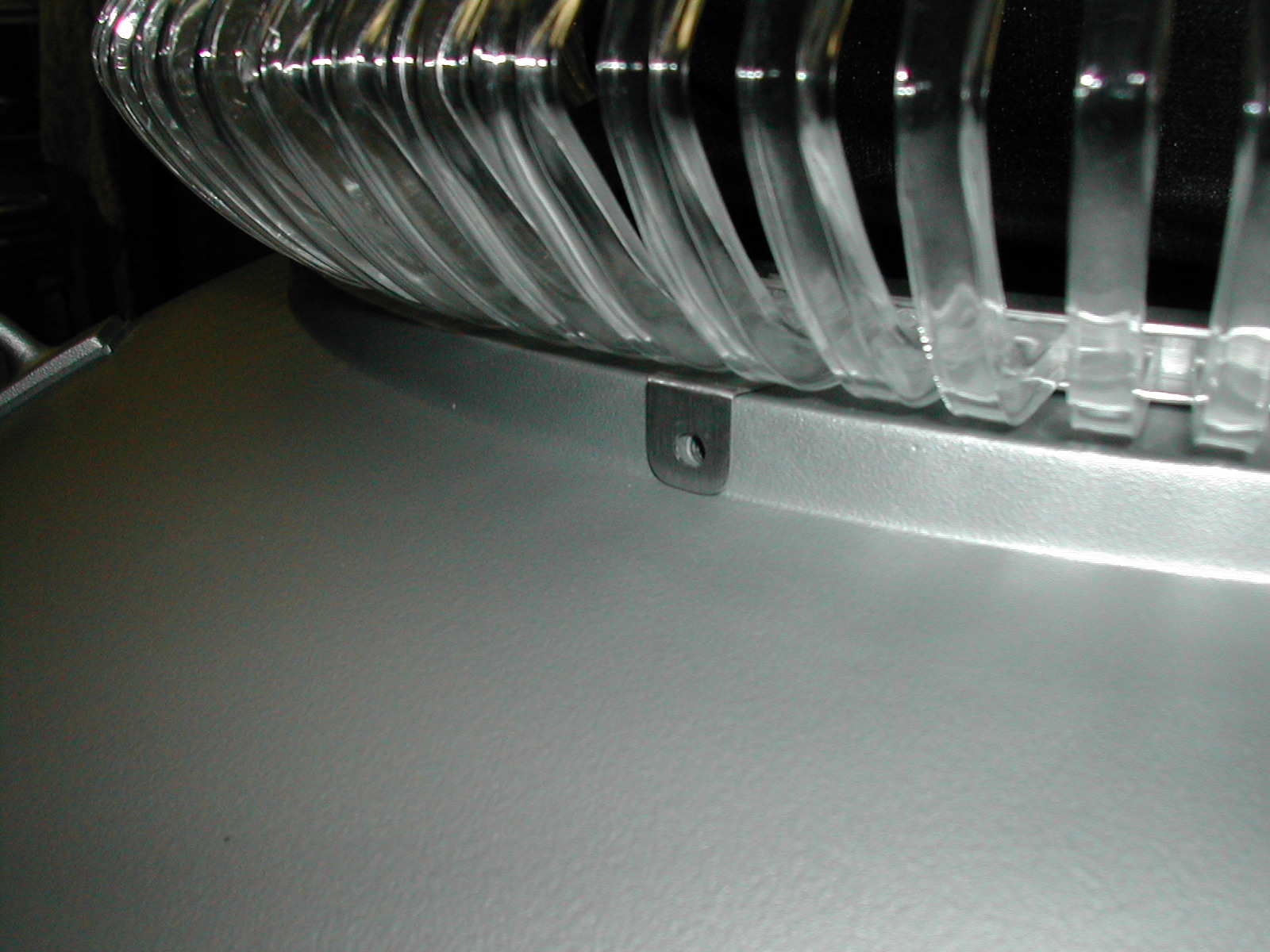
6. Drill holes to accept screws to hold the collar latches, as in Craig Reinbrecht's robot.
7. Drill horizontal hole through the back of the torso neck ring to accept the fastening screw for the collar, as in Craig Reinbrecht's robot:
8. Remake
the neon backplate.
The standard backplate that nearly all B9 robot
builders have been using does not fit the torso properly. Look at the
unsightly
and unnecessary gaps between the backplate and the torso:
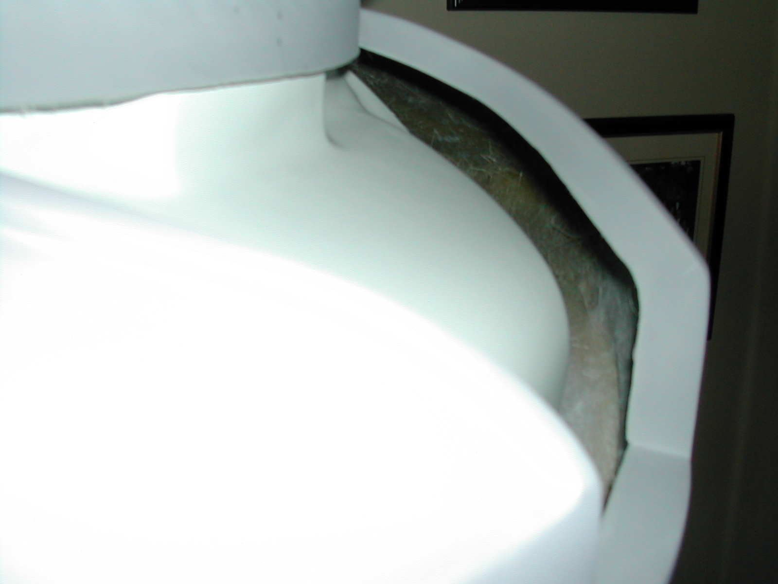
There is no reason for these gaps. They did not exist in the original robot. In fact, the neon tubes were tight up against the torso in the original, as these photos illustrate:

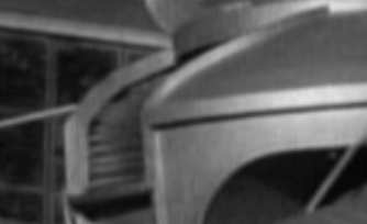
Another thing that I have noticed is that the
bottom most neon tube is just above the lower lip of the robot's
"mouth."
My neon backplate is so constructed that the bottom most neon tube
would
fall below this lip. Clearly, I will have to remake the neon backplate.
9. Fit
the acrylic vents with their aluminum sliding
channels into the torso
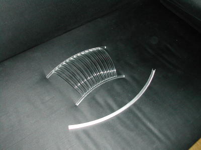
The four acrylic vents as well as their aluminum
sliding channels were designed and built by Craig Reinbrecht. One can
well
appreciate the difficulty in building acrylic vents that have exactly
the
right curve so that they match the inner curve of the robot's torso
perfectly.
Building a Lost in Space robot from scratch gives one a lot of
personal
pride of accomplishment, but it is also a great relief knowing that
master
craftsmen have already solved some of the most problematic building
difficulties
and that they are willing to share their expertise and the fruits of
their
labors.
10.
Attach the programming bay
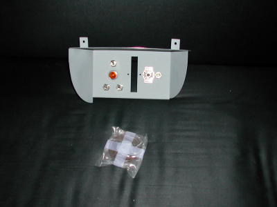
This beautiful piece of workmanship was designed
and built by Craig Reinbrecht. The right side wall of the programming
bay
is smaller then the left wall so that an aluminum channel for the
acrylic
vent can be fitted to it. The larger left wall acts as a break for the
vent, preventing it from sliding to the left.
11. Have
the torso professionally painted by an
auto body shop
I have decided that I will not have the torso,
or any other part of the robot, textured. There is no question but that
the torso and other parts of the original robot costume were textured
before
painting. This served to reduce and eliminate glare from studio lights
reflecting off the robot and bouncing into the motion picture camera
lens.
Texturing also served the very useful purpose of reducing the
visibility
of flaws, repairs, and damage. It is unlikely, though, that a real
robot
would be textured in this same way. Bearing this in mind, my robot will
remain free of texturing. I fully respect those builders who elect to
add
texturing to their robot's torso, but my robot, as I have stated
elsewhere,
is intended to be a realization of the robot from
Lost in Space
as if it had been a real robot rather than a costume and stage
prop
in a television series.
12. Install the electronic components