ALUMINUM
RADAR
Now Ready!
| Home | Back | Previous Page | Next Page | October Progress Page |
ALUMINUM
RADAR
Now Ready!
I picked up two completed aluminum radars from my machinist today. They are both for sale. My own radar is still being completed. It should be ready in about two weeks. The delay is due to the anodization process that I have chosen for my own radar.
As you will have read in the radar update in my October progress section, I have had these radars manufactured out of 2024 aluminum. Each radar weighs just under ten pounds. The radar was made using Dave Painter's robot blueprints. The only deviation from these blueprints is the canting of the top ring. This alloy can be anodized without discoloration, but it is just as beautiful in its raw state. The following photographs depict the radars in their pristine, unanodized, unbeadblasted state. I like the look of the raw aluminum so much that I have been tempted to forgo anodization.
Click on
the thumbnail image to see the full-size
photograph
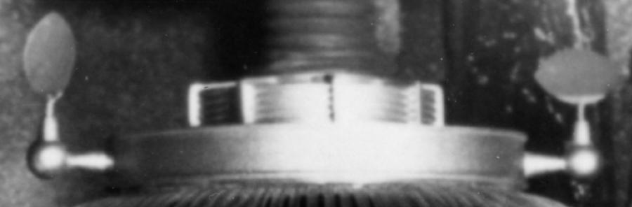
 Here is the assembled radar
sitting atop a beautiful Lorenzo d'Alessandro
laser-cut collar. The radar is obviously heavier than an acrylic radar,
but it places no strain of any kind on the collar. The d'Allessandro
collar,
I should point out, is made incredibly sturdy by hidden vertical
reinforcing
rods on the interior. It is the perfect collar for my aluminum radar.
The
fine rubber bubble lifter is a Dewey Howard creation. Look closely, and
you can see the gentle radius on the top corner of each vane. A fine
craftsman
touch added by my machinist.
Here is the assembled radar
sitting atop a beautiful Lorenzo d'Alessandro
laser-cut collar. The radar is obviously heavier than an acrylic radar,
but it places no strain of any kind on the collar. The d'Allessandro
collar,
I should point out, is made incredibly sturdy by hidden vertical
reinforcing
rods on the interior. It is the perfect collar for my aluminum radar.
The
fine rubber bubble lifter is a Dewey Howard creation. Look closely, and
you can see the gentle radius on the top corner of each vane. A fine
craftsman
touch added by my machinist.
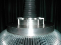
 Here is another shot of the radar with the bubble
lifter removed. You can
see the nice taper to the center ring. Many thanks to builder Marc
Chabot
for pointing out this feature on the hero robot costume. Thanks also to
Michael Davis for highlighting this often overlooked detail of the
radar
of the stunt robot on his website.
Here is another shot of the radar with the bubble
lifter removed. You can
see the nice taper to the center ring. Many thanks to builder Marc
Chabot
for pointing out this feature on the hero robot costume. Thanks also to
Michael Davis for highlighting this often overlooked detail of the
radar
of the stunt robot on his website.
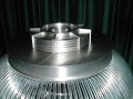
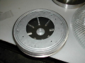
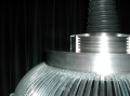
 Here is another shot of the radar, revealing the ten
discs of the clutch
pack.
Here is another shot of the radar, revealing the ten
discs of the clutch
pack.
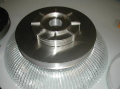
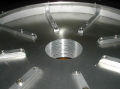 In this shot of the radar turned upside down, you can
see the eight internal
ribs that hold the entire radar together. Hidden screws pull all the
pieces
tightly together. One ring of screws terminates within the eight vanes.
The other ring of screws terminate within the top ring. My machinist
said
that he was able to assemble the radar in ten minutes. The advantage of
using screws is that the radar can easily and quickly be disassembled
if
one ever wanted to make modifications to it. If you wanted to reduce
the
weight of the radar, you could unbolt the radar, and then cut away
internal
sections of the clutch pack.
In this shot of the radar turned upside down, you can
see the eight internal
ribs that hold the entire radar together. Hidden screws pull all the
pieces
tightly together. One ring of screws terminates within the eight vanes.
The other ring of screws terminate within the top ring. My machinist
said
that he was able to assemble the radar in ten minutes. The advantage of
using screws is that the radar can easily and quickly be disassembled
if
one ever wanted to make modifications to it. If you wanted to reduce
the
weight of the radar, you could unbolt the radar, and then cut away
internal
sections of the clutch pack.
 The radar has been designed to work with the Rockler
12" turntable. In
this shot, the radar is upside down and the Rockler turntable has been
put in position.
The radar has been designed to work with the Rockler
12" turntable. In
this shot, the radar is upside down and the Rockler turntable has been
put in position.
 Here, you can see how the screw holes in the Rockler
turntable line up
with screw holes in the bottom plate of the radar. Four bolts (supplied
by the machinist for free) hold the turntable to the radar.
Here, you can see how the screw holes in the Rockler
turntable line up
with screw holes in the bottom plate of the radar. Four bolts (supplied
by the machinist for free) hold the turntable to the radar.
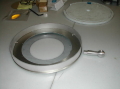 In this shot, the turntable has been place face side
up. I have placed
the bottom plate and vertical band from my own unfinished radar on top
of the radar to illustrated how everything fits together. The machined
spinner post depicted in the photograph was made using the dimensions
provided
in Dave Painter's blueprints.
In this shot, the turntable has been place face side
up. I have placed
the bottom plate and vertical band from my own unfinished radar on top
of the radar to illustrated how everything fits together. The machined
spinner post depicted in the photograph was made using the dimensions
provided
in Dave Painter's blueprints.
For my
own radar, holes will be drilled into the
vertical band to receive the peg of the machined spinner posts. The peg
will have threads cut into it so that the spinner post can be held
tightly
and securely in place by a hidden nut on the inside of the radar. This
is an ingenious concept invented by my brilliant machinist.
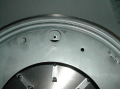
 In this photograph, you can see the one minor flaw in
the aluminum radar.
A tiny hairline wrinkle is visible where the vertical band has been
welded
on the inside. The glaring flash on my camera makes the flaw seem worse
than it really is. This flaw is nearly invisible unless it is pointed
out.
I will be placing this weld seam at the back of the radar, so no one
will
ever see it anyway. Bead blasting, buffing, or painting would probably
cover all traces of this seam.
In this photograph, you can see the one minor flaw in
the aluminum radar.
A tiny hairline wrinkle is visible where the vertical band has been
welded
on the inside. The glaring flash on my camera makes the flaw seem worse
than it really is. This flaw is nearly invisible unless it is pointed
out.
I will be placing this weld seam at the back of the radar, so no one
will
ever see it anyway. Bead blasting, buffing, or painting would probably
cover all traces of this seam.
What
remains to be done?
1. Machining of new spinner posts using Craig
Reinbrecht's blueprint for a first-season spinner post. Spinner
posts
will have threaded pegs as explained above.
2. Anodizing of all parts of my radar, including
the spinner posts
3. Attachment of brackets on the inside of my
radar to hold the Warner Electric
linear actuator
motor that will lift the bubble.
4. Attachment of brackets on the Rockler
turntable
to hold the motor that will spin the radar.